ВАЖНЫЕ ЗАМЕЧАНИЯ ПРИ ПРОЕКТИРОВАНИИ И МОНТАЖЕ ЛИНЕЙНЫХ ТЕПЛОВЫХ ИЗВЕЩАТЕЛЕЙ В СООТВЕТСТВИИ С TCVN 7568-14:2025
IMPORTANT NOTES WHEN DESIGNING AND INSTALLING LINE-TYPE HEAT DETECTORS ACCORDING TO TCVN 7568-14:2025
- 1 Fire Safety Institute of the Ministry of Defense of Vietnam, Vietnam Fire and Rescue Police Department
- 2 Fire Safety Institute of the Ministry of Defense of Vietnam
Линейные тепловые извещатели являются важным элементом автоматических систем пожарной сигнализации, особенно эффективным в длинных, узких, запылённых или агрессивных средах, где надёжное обнаружение пожара затруднено. Однако проектирование и установка таких систем в соответствии с новыми стандартами остаются сложной задачей. В данной статье анализируются конструктивные и функциональные принципы линейных тепловых извещателей и выделяются ключевые аспекты, которые необходимо учитывать при их проектировании и монтаже.
Line-type heat detectors are a vital component of automatic fire alarm systems, particularly effective in long, narrow, dusty, or harsh environments where reliable detection is difficult. However, designing and installing such systems in compliance with the new standards remains challenging. This paper analyzes the structural and operational principles of line-type heat detectors and highlights key considerations for their design and installation.
8) ВАЖНЫЕ ЗАМЕЧАНИЯ ПРИ ПРОЕКТИРОВАНИИ И МОНТАЖЕ ЛИНЕЙНЫХ ТЕПЛОВЫХ ИЗВЕЩАТЕЛЕЙ В СООТВЕТСТВИИ С TCVN 7568-14:2025
ИД: 2551 Авторы: Нгуен Хыу Ан | Буи Тхи Хиен | Ву Куанг Тханг |
Important notes when designing
and installing linear heat detectors
in accordance with TO TCVN 7568-14:2025
Linear heat detectors are an essential element of automatic fire alarm systems, particularly effective in long, narrow, dusty, or aggressive environments where reliable fire detection is difficult. However, designing and installing such systems in accordance with new standards remains a complex task. This article analyzes the design and functionality of linear heat detectors and highlights key aspects that must be considered during their design and installation.
Keywords: linear heat detectors, design, installation.
ВАЖНЫЕ ЗАМЕЧАНИЯ ПРИ ПРОЕКТИРОВАНИИ
И МОНТАЖЕ ЛИНЕЙНЫХ ТЕПЛОВЫХ ИЗВЕЩАТЕЛЕЙ
В СООТВЕТСТВИИ С TCVN 7568-14:2025
Линейные тепловые извещатели являются важным элементом автоматических систем пожарной сигнализации, особенно эффективным в длинных, узких, запылённых или агрессивных средах, где надёжное обнаружение пожара затруднено. Однако проектирование и установка таких систем в соответствии с новыми стандартами остаются сложной задачей. Анализируются конструктивные и функциональные принципы линейных тепловых извещателей и выделяются ключевые аспекты, которые необходимо учитывать при их проектировании и монтаже.
Ключевые слова: линейные тепловые извещатели, проектирование, установка.
1. Introduction
The automatic fire alarm system is a crucial link in fire safety, responsible for quickly and accurately detecting and reporting incidents, as well as activating relevant technical systems to minimize damage to people and property. The system’s reliability mainly depends on design, equipment, installation methods, and maintenance.
Currently, line-type heat detectors stand out due to their continuous structure, allowing monitoring of long, narrow, or harsh environments such as cable tunnels, warehouses, and dusty factories, where conventional point-type detectors are less effective. Their ability to operate reliably in high-temperature, dusty, and vibrating conditions makes them a suitable solution for special fire protection requirements.
However, designing and installing fire alarm systems with line-type heat detectors under the new standard TCVN 7568-14:2025 Automatic fire detection and alarm systems – Part 14: Design, installation, commissioning, and service of fire detection and fire alarm systems in and around buildings still poses difficulties. This paper therefore analyzes the structure and working principles of these devices and highlights essential design and installation considerations to improve system effectiveness and reliability.
2. Overview of Line-Type Heat Detectors
A line-type heat detector is a device capable of detecting an increase in temperature at any point along its length. The detector generates an electrical signal transmitted to the fire alarm control panel when the ambient temperature reaches its activation threshold. According to the method of location identification, there are two types of line-type heat detectors: addressable line-type heat detectors and non-addressable line-type heat detectors.
Non-addressable line-type heat detectors:
Structure: This type of line-type heat detector consists of four main components: an outer polymer sheath, a protective tape, a heat-sensitive polymer layer, and a metallic core.
The outer polymer sheath serves to protect the internal components. Since this layer is directly exposed to various installation environments, the selected polymer must be resistant to chemical corrosion and ultraviolet radiation. Each type of line-type heat detector cable has a different outer sheath material, designed to suit specific conditions and installation environments (Figure 1).
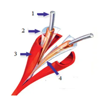
Figure 1. Structure of a line-type heat detector cable
1. Metallic core; 2. Protective tape 3. Outer polymer sheath
4. Heat-sensitive polymer sheath
Operating principle: Under normal conditions, this line-type heat detector is installed to form a closed circuit with an end-of-line resistor. In the standby mode, a small current constantly flows through the circuit to monitor the operation of the devices. If faults such as open circuits, wire breaks, or loss of resistance occur, the system will switch to the fault condition.
When a fire occurs, the rising ambient temperature acts on the detector. At the point where the temperature reaches its operating threshold, the heat-sensitive polymer layer changes its property from an insulator to a conductor, causing the two metallic cores to short-circuit. This short-circuit generates a fire alarm signal that is transmitted to the fire alarm control panel. The control panel then processes the signal, switching from standby mode to fire alarm mode, and simultaneously activates audible and visual warning devices.
Addressable line-type heat detectors:
Structure: In practice, an addressable line-type heat detector is essentially an optical fiber cable combined with a location-determining device that uses the Raman optical backscattering phenomenon. This system is known as a Distributed Temperature Sensing (DTS) system. It has the function of monitoring temperature along the entire length of the detector with high accuracy. The DTS system consists of control software, a transmitter, a receiver, and a digital processor
In this system, the optical fiber cable is structured as follows: it consists of a core (responsible for transmitting light signals, with refractive index n₁), a cladding layer (with refractive index n₂ < n₁, surrounding the core), and an outer coating (which eliminates stray refracted rays, and protects the fiber against moisture, scratches, and bending). Outside of these layers, there is a strength member (providing mechanical strength and heat resistance) and a protective sheath (resistant to impact, heat, and abrasion, shielding the internal parts from moisture and environmental effects) (Figure 2).
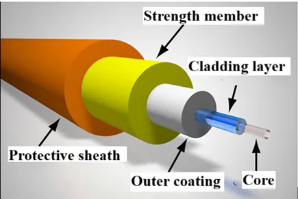
Figure 2. Structure of an optical fiber cable
Operating principle: Under normal conditions, the transmitter emits a laser beam at a specific frequency determined by the manufacturer. When a fire occurs, the heat affects the fiber optic core, locally altering the optical transmission characteristics of the cable. The increase in temperature at any point causes the material particles in that area to vibrate, and as the laser light passes through this vibrating region, interactions occur between photons and molecules. At this stage, backscattered light appears in the fiber in the opposite direction of the incident beam, a phenomenon known as Raman scattering. Raman scattering consists of three components: Rayleigh scattering, which has the same wavelength as the laser source, Stokes scattering, with a longer wavelength, and anti-Stokes scattering, with a shorter wavelength. The intensity of the anti-Stokes component depends on temperature, while the Stokes component is independent of it. Consequently, the local temperature at the fire point is calculated from the ratio between the intensities of the anti-Stokes and Stokes components. When the temperature reaches the alarm threshold, the detector switches to fire alarm mode and simultaneously displays both the temperature and the location along the cable where the alarm is triggered. This location is determined by the time difference between the emission of the laser pulse and the reception of the backscattered signals.
3. Some notes on designing and installing line-type heat detectors:
At present, due to their particular effectiveness in special environments where conventional detectors cannot function properly, line-type heat detectors are increasingly prioritized in automatic fire alarm systems. However, the design and installation of these detectors still face many difficulties. Therefore, in order to help address the challenges mentioned above, it is essential first to comply with the provisions of TCVN 7568-14:2025 [1] on the design and installation of fire detection and alarm systems for buildings and structures.
In terms of design, several additional points should be observed.
First, it is necessary to enhance understanding of the operating principles and functional characteristics of different types of line-type heat detectors in order to select the model most suitable for the architectural features and fire hazards of the protected area. Line-type heat detectors are commonly used to protect areas of great length, narrow spaces, dusty conditions, or harsh environments where conventional detectors are less effective. Furthermore, when selecting line-type heat detectors for design and installation, it is essential to base the choice on Annex A of TCVN 7568-14:2025 [1], while also considering the nature of the combustible materials and the characteristics of the protected environment, so as to avoid false alarm situations.
Second, in design and installation, the maximum protection area of line-type heat detectors must comply with the limits of the fire detection zone specified in Clause 5.7.2 of this standard [1]. Specifically, the area of a fire detection zone within a building or facility must not exceed 2000 m². For floors with discontinuous areas, an additional condition must be satisfied: the maximum dimension of a fire detection zone shall not exceed 100 m, the distance between adjacent entrances shall not exceed 10 m, all entrances must be visible to each other, and the zone must be confined within a single floor. For areas without internal entrances, independent fire detection zones must be arranged, separate from those with internal access. In the case of mezzanine floors directly accessible from the common floor, the mezzanine may share the same detection zone; enclosed spaces not exceeding 500 m² may also be combined into the same floor’s detection zone, provided that the total number of detectors does not exceed 40. In addition, multiple detection zones may be grouped into one fire alarm zone, but a single detection zone shall not be divided into multiple alarm zones (Figure 3).
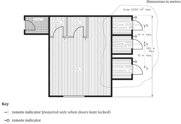
(a) Industrial
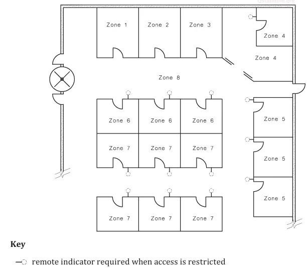
(b) Retail/Commercial
Figure 3. Example detection zone allocation for contiguous and non-contiguous areas [3]
Third, since a line-type heat detector is composed of multiple components, each component is considered equivalent to a point-type detector when determining spacing. In design, these line-type heat detectors must be arranged throughout the entire fire detection zone, ensuring that the distance between two adjacent lines does not exceed 7.2 m and that the distance from any wall or partition does not exceed 3.6 m. In addition, the spacing between detectors must be reduced by 30 % when the ceiling is divided by structural elements such as beams, girders, or pipes with a vertical depth greater than 0.3 m [1].
Fourth, line-type heat detectors must be installed at every ridge of the roof space, even when the distance between ridges is less than 7.2 m, and they must also be placed near the ridge of sloped roofs, roof surfaces, or flat surfaces in order to avoid dead air spaces [1].
In addition, to ensure the effective operation of line-type heat detectors, several further considerations must be followed during installation:
First, for road tunnel projects, fire alarm systems using line-type heat detectors must be designed and installed to cover the entire traffic space as well as the associated technical rooms. The heat-sensing cable should be arranged along the tunnel ceiling or along both tunnel walls, with preference given to two parallel runs in long tunnels to enhance reliability and reduce the risk of blind spots. The spacing of clamps, bending radius, connection methods, maximum length per detection zone, and the avoidance of obstructions along the transmission path must all comply with regulations, with the cable length per zone typically limited to about 1.5–3 km depending on the manufacturer [4] (Figure 4).
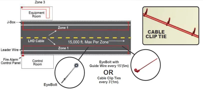
Figure 4. Illustration of the arrangement of linear heat detector cables in a tunnel (source [4])
Second, in areas such as false ceilings, raised floors, and elevator shafts, line-type heat detector cables must be installed along the technical voids, positioned directly above electrical cable trays and piping routes, or run along the shaft walls to ensure comprehensive monitoring capability.
Third, to ensure early fire detection in cold storage environments with low temperatures and high humidity, line-type heat detector systems must be designed and installed in accordance with standards, while strictly following the technical catalogue of the selected manufacturer. The cables must be of a specialized type capable of withstanding deep sub-zero conditions (down to approximately –40 °C) and must have an activation threshold at least 17–28 °C higher than the ambient temperature, commonly around 68 °C [5]. The sensor cable should be placed close to the roof or along the walls where smoke and hot gases accumulate first. When attached to sprinkler piping, the cable must be fixed with double loops at intervals of about 0.9 m to avoid direct contact with the pipe and local overheating [5].
Fourth, the installation of line-type heat detectors must avoid any mechanical impact that could damage the sensing elements. The heat-sensing cable must be securely fixed using clamps or hangers to prevent sagging, and when bending is required, the minimum bending radius must be 15–20 times the cable diameter (equivalent to 60–80 mm). At the same time, installation should avoid locations exposed to mechanical collision or direct radiant heat (such as near lighting fixtures or exhaust pipes). When passing through walls or floors, the cable must be routed inside protective conduits.
4. Conclusion
This paper has analyzed the structural characteristics, operating principles, and technical requirements of line-type heat detectors, while also presenting several important recommendations to make the design and installation process more accurate and appropriate. In addition to the above considerations, it is essential to comply with the technical specifications provided by the manufacturer in order to ensure early fire detection, thereby minimizing damage and safeguarding both people and property.
References
- Ministry of Science and Technology (2025). TCVN 7568-14:2025 Automatic fire detection and alarm systems – Part 14: Design, installation, commissioning, and service of fire detection and fire alarm systems in and around buildings.
- Nguyen Duc Anh, Dang Nhu Dinh, Pham Van Thanh (2018). Automatic Fire Alarm Systems – Textbook. People’s Police Publishing House, Hanoi.
- ISO 7240-14:2013. Fire detection and alarm systems – Part 14: Design, installation, commissioning, and service of fire detection and fire alarm systems in and around buildings.
- SAFE Fire Detection Inc. (2025). ASD & LHD Handbook 2024 v1.0.
- Manufacturers’ catalogues.